Davac5: Difference between revisions
Jump to navigation
Jump to search
| Line 86: | Line 86: | ||
* '''REC''' - Recording input to record band traffic | * '''REC''' - Recording input to record band traffic | ||
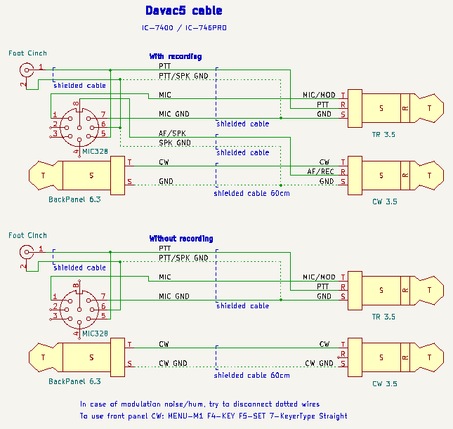
==Example for IC7400== | |||
[[Image:Davac5-IC7400.png]] | [[Image:Davac5-IC7400.png]] | ||
==Yaesu== | |||
When use dynamic microphone, cut JP2 to break DC bias. | |||
==LEDs== | ==LEDs== | ||
Revision as of 20:33, 1 August 2024
Davac 5 is new design of voice/SSB keyer for Tucnak. Although version 5 may appear to be a successor to version 4, is not true. It brings some advantages but also lacks some features.
To choose the version that best suits your requirements, please look at the table:
| Davac 5 | Davac 4 | |
|---|---|---|
| Size | small | bigger |
| Drivers required | No | Yes |
| Isolated | No, use the USB isolator | Yes |
| Band output | No | Yes |
| USB | Micro-B or A male | B |
| Soundcard | Is the soundcard itself | Uses PC soundcard |
| Audio cables | Shorter | Longer |
| Modulation relay | Solid SPST | Mechanical SPDT |
| Separated grounds | No | Yes |
Photos
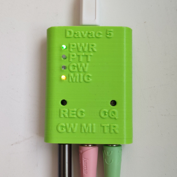
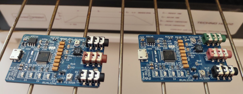
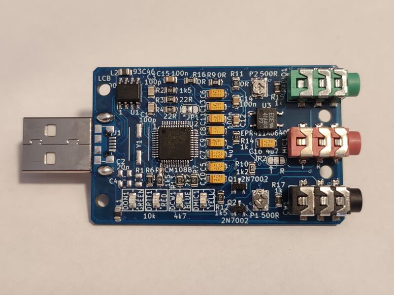
Features
- Simple assembly
- All parts are SMD
- Designed for SMD reflow
- 3.5 jacks
- 3D printed box
- SMD LEDs + light guides on the top side
- power supply from USB
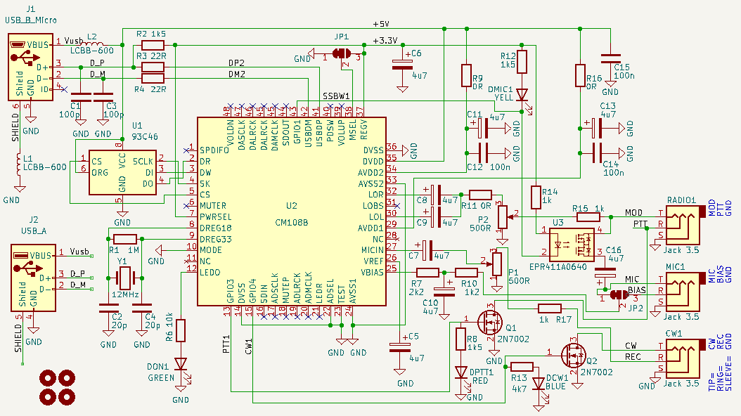
Circuit diagram
Notes
- R1, Y1, C2, C4 are not assembled in case of CM108B
- Althrough preferred chip is the CM108B, is possible to assembly older CM108
- The 93C46 is optional but recommended
- The JP1 - Turns ON/OFF the audio mixer - please consult datasheet of the CM108B
- I used LCBB-600 also instead of R9 and R16
- R11 and R17 are for possible coarse attenuation
Connecting to the radio
- MOD - Modulation output to the microphone input of radio
- PTT - Push to talk output to switch Radio to the transmit (active low)
- GND - One ground (ground plane on the bottom layer)
- MIC - Modulation input from headset
- BIAS - Microphone supply (from soundcard, not from radio)
- CW - CW output to key to the radio
- REC - Recording input to record band traffic
Example for IC7400
Yaesu
When use dynamic microphone, cut JP2 to break DC bias.
LEDs
- PWR lights up - Device is powered from USB
- PWR blinks - Soundcard is playing or recording
- PTT - Push to talk is active (SSB and also CW)
- CW - CW in the rhytm of Morse code
- MIC - The SSR connects MIC to the MOD (off/disconnected if CQ is active)
Trimmers
- CQ - Modulation level to the Transceiver
- REC - Record level attenuator
PCB
![]() Gerber files to order PCB at Elecrow or jlcpcb.com.
Gerber files to order PCB at Elecrow or jlcpcb.com.
Box
Recommendations:
- Nozzle 0.4mm
- No support, maybe brim in case of bad adhesion
- Layer height - first 0.3mm, others 0.2mm
- PETG or PLA
Light guides are made from transparent PETG filament.
Parts
![]() Bill of material for tme.eu .
Bill of material for tme.eu .
(not including cables)
Set USB string to EEPROM
Only if the 93C46 is installed. From menu Setup, CW keying, Davac5 options.

Post production inspection
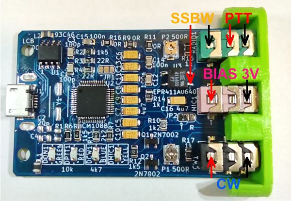
- Connect device to computer. The green LED lights up.
- Start Tucnak. Go to CW keying, set Enable and Davac5.
- Go to Audio, Choose Davac 5.1 for playback and capture.
- Connect headphones to green jack (RADIO1). Run SSB CQ (You will hear it weak beacause impedance do not match headphones)
- Take multimeter, set it to diode measure with buzzer. Look at image above.
- Connect measuring needles to PTT points. Use TAB key in Tucnak to turn TX ON. The red LED lighs up and multimeter will beep.
- Press ESC to RX. Connect needles to SSBW points. Buzzer will beep together with yellow LED. Run SSB CQ (F5), LED and buzzer will OFF.
- During SSB CQ (or SSB recording) the green LED blinks.
- Press Alt+M for CW. Connect multimeer to CW points. Run CW CQ (F5). Multimeter will beep together with blue LED.
- Switch multimeter to Voltage measure to >3V range (4V, 20V...). Measure points BIAS. Voltage must be around 3V.
